Mathematical model of excitation-contraction in a uterine smooth muscle cell
Abstract
The Bursztyn et al. (2007) paper proposes a mathematical model of excitation-contraction in a myometrial smooth muscle cell (SMC). The model incorporates processes of intracellular concentration control, myosin light chain (MLC) phosphorylation and stress production. We create a modularized CellML implementation of the model, which is able to simulate these processes against the original data.
1Introduction
The model Bursztyn et al., 2007 describes how the intracellular concentration increases due to membrane depolarization, which leads to an increase in the myosin phosphorylation rate and therefore the generation of muscle contraction. Here, we divide the mathematical model into distinct sub-modules encoded in CellML enabling reuse of the various sub-modules in future studies and models. We also reuse a few previously developed sub-modules at https://
2Model description
2.1Primary Publication
The model Bursztyn et al., 2007 incorporates three control mechanisms: voltage-operated channels, pumps and / exchangers, which employ the mathematical formulation proposed in Parthimos et al. (1999). The cross-bridge model of Hai & Murphy (1988) is used to describe the processes of myosin light chain (MLC) phosphorylation and stress production, which is essentially a deterministic multi-state Markov model (MM) Sakmann & Neher, 1996. The primary paper Bursztyn et al., 2007 has shown that the model is able to reproduce the results against experimental data obtained in pregnant rats and measurements in human nonpregnant myometrial cells. There is no publicly available code for this model, making it difficult to reuse this work. We therefore present in this article a CellML implementation for researchers to reuse in further developments based on this model.
2.2Modularized CellML model
The modularized CellML implementation is available in the Physiome Model Repository (PMR) at https://
The J_Ca component defines the fluxes of ions, including the flux through the L-type voltage dependent channels , the efflux through pump , and the flux through the exchangers . The computation of current through the L-type voltage dependent channels reuses the imported ionic current component ( https://
The EC_uSMC component combines the excitation description J_Ca component, the reversal potential defined in the Nernst potential component, and the imported CB4HM component ( https://
To test individual processes, we built the Unit_uSMC component, which decouples the connection between the excitation and contraction, thus enabling the use of an arbitrary profile to validate the response of phosphorylation and stress development.
Following best practices, our CellML implementation separates the mathematics from the parameterisation of the model. The mathematical model is imported into a specific parameterised instance in order to perform numerical simulations. The parameterisation would include defining the stimulus protocol to be applied. We have seven sets of simulation experiments and corresponding simulation results to reproduce the corresponding figures in the primary publication:
- the single stimulation experiment is used to validate the excitation and contraction response to a single voltage pulse with various durations and levels;
- the multiple stimulation experiment is used compare the reaction to the voltage-pulse train with a single pulse;
- the voltage ramp experiment is used to compute the channel activation as a function of ;
- the membrane potential simulation experiment is used to simulate the excitation and contraction response to a recorded human plateau potential;
- the experiment is used to evaluate the variation in the flux through the exchangers as a function of ;
- the experiment 1 is used to simulate the reaction in human nonpregnant myometrium to an increase in ; and
- the experiment 2 is used to simulate the reaction during stretch-induced phasic contraction of human myometrium.
Simulation settings and detailed solver information are encoded in SED-ML documents for execution of the simulation experiments Waltemath et al., 2011. The Python scripts used with OpenCOR Snapshot 2021-05-19 Garny & Hunter, 2015 to perform simulations and produce the figures in the primary paper are also included in the folder ./Simulation/src. The name of the simulation and plot scripts indicates the figure number in the primary paper. For example, Fig2_sim.py is used to generate the simulation data and Fig2_plot.py reproduces the graph shown in Figure 2 from Bursztyn et al. (2007).
3Model results
In the presented figures, the dots denote the simulated data extracted from the primary publication, while the solid lines are the simulation results produced by the current CellML implementation.
3.1Control of Intracellular Concentration
To simulate the intracellular concentration decay, we need to increase the first. In the experimental paper Shmigol et al., 1998, they used a train of pulses from a holding potential of mV to a step potential of mV to generate an increase in . In our simulation of Figure 2A, we set the value at time to the experimentally measured one, i.e., nM, and simulate the subsequent decay due to extrusion of by the exchangers only. Figure 2B describes a second simulation under similar conditions but with both extrusion mechanisms (exchanges and pumps) active. The membrane potential throughout the simulation holds at mV and the corresponding is mM.
In the simulation of Figure 3 from the primary paper, the holding voltage is mV and the corresponding is mM. At time , the initial value of is set to nM, while a -ms pulse voltage is applied. The potential levels vary from plot A to C. Figure 4 uses the similar settings with different pulse potentials as well.
The experiment setting is summarized in Table 1 and the simulation results are shown in Figures 1, 2 and 3.
Table 1:Experiment setting
| Fig | Test voltage (mV) | Pulse duration (ms) | (mM) | Initial (nM) |
|---|---|---|---|---|
| 2A | NA | NA | 16.55 | 980.63 |
| 2B | NA | NA | 16.55 | 980.63 |
| 3A | 0 | 200 | 2.9836 | 130 |
| 3B | 10 | 200 | 2.9836 | 130 |
| 3C | -10 | 200 | 2.9836 | 130 |
| 4A | -20 | 200 | 2.9836 | 130 |
| 4B | 20 | 200 | 2.9836 | 130 |
![Simulations of [Ca_{i}^{2+}] decay (in nM). A: under inhibition of Ca^{2+} pumps. B: in control conditions (c.f., Fig. 2 in ).](https://pub.curvenote.com/4b04def0-9832-43bc-89b7-d4a0fb6b4036/public/simFig2-d9d9ea6b9cc2ee123dfa38b6ea2df3fa.png)
Figure 1:Simulations of decay (in nM). A: under inhibition of pumps. B: in control conditions (c.f., Fig. 2 in Bursztyn et al. (2007)).
![Simulation of [Ca_{i}^{2+}] rise and decay following a 200-ms voltage pulse of 0 mV (A), 10 mV (B), and -10 mV (C) (c.f., Fig. 3 in ).](https://pub.curvenote.com/4b04def0-9832-43bc-89b7-d4a0fb6b4036/public/simFig3-15d8af5353779df6f833acb7684d8916.png)
Figure 2:Simulation of rise and decay following a -ms voltage pulse of mV (A), mV (B), and mV (C) (c.f., Fig. 3 in Bursztyn et al. (2007)).
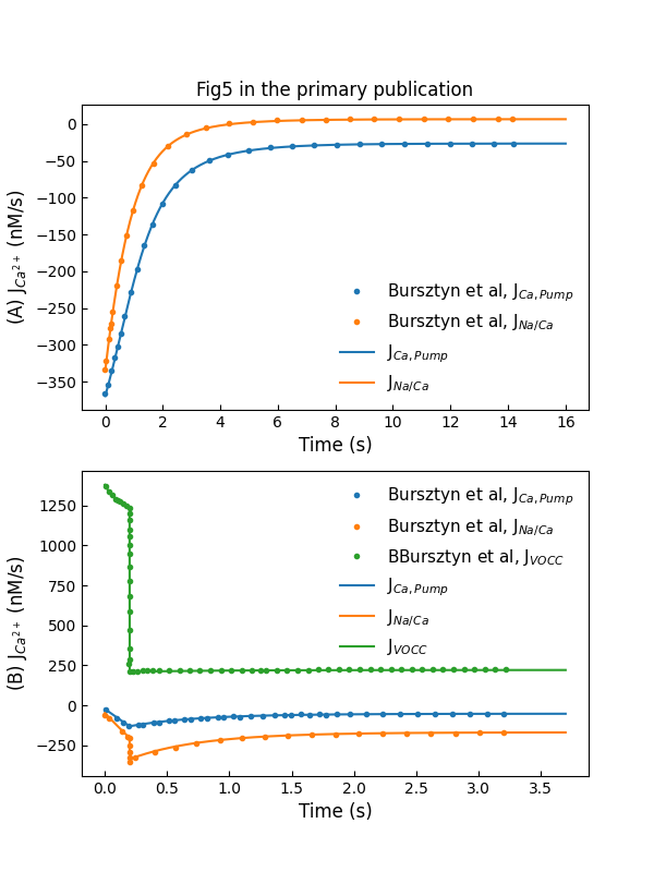
The experiment setting to reproduce primary Figure 5A and 5B are the same as the one used in primary Figure 2B and Figure 3A, respectively. The simulation results are shown in Figure 4. Plot A shows flux through exchangers and pumps during decay at a holding voltage of mV, while plot B shows flux through channels and extraction mechanisms during rise and decay in response to a -ms voltage pulse to mV from holding potential of mV.
![Simulation of [Ca_{i}^{2+}] rise and decay following a 200-ms voltage pulse of -20 mV (A), 20 mV (B) (c.f., Fig. 4 in ).](https://pub.curvenote.com/4b04def0-9832-43bc-89b7-d4a0fb6b4036/public/simFig4-dd9e8b9a4ffc683ad318cacccc06981c.png)
Figure 3:Simulation of rise and decay following a -ms voltage pulse of mV (A), mV (B) (c.f., Fig. 4 in Bursztyn et al. (2007)).

Figure 4:Simulations of fluxes through various control mechanisms, including entry and extraction from the cell (c.f., Fig. 5 in Bursztyn et al. (2007)).
Figure 5 shows the model reaction to a train of pulse potentials.
![Simulation of [Ca_{i}^{2+}] rise and decay in response to a train of 10 voltage pulses of 100 ms duration from a holding potential of -80 mV to a pulse potential of 0 mV, with an interval of 330 ms between the pulses (c.f., Fig. 6 in ).](https://pub.curvenote.com/4b04def0-9832-43bc-89b7-d4a0fb6b4036/public/simFig6-7495745308fd940991f50c303724e605.png)
Figure 5:Simulation of rise and decay in response to a train of 10 voltage pulses of ms duration from a holding potential of mV to a pulse potential of mV, with an interval of ms between the pulses (c.f., Fig. 6 in Bursztyn et al. (2007)).
3.2Sensitivity Analysis
The effect of parameter and intracelluar concentration is shown in Figure 6 and Figure 7. Figure 6A and Figure 7A simulations are performed on a holding potential of mV and the experiment setting is listed in Table 2. We provide a voltage ramp ranging from mv to mV to compute the activation function in Figure 6B. While the linear from mM to mM is created to compute the flux in Figure 7B, the membrane potential holds at mV.
Figure 6A shows the variation in decay following a -ms voltage pulse to mV due to changes in , while the variation in the activation function in Figure 6B indicates the fractional amount of open VOCCs.
Figure 7A shows the variation in rise and decay following a -ms voltage pulse to mV due to changes in , while Figure 7B shows the variation in the flux through exchangers.
Table 2:Experiment setting
| Fig | Test voltage (mV) | Pulse duration (ms) | (mM) | Initial (nM) |
|---|---|---|---|---|
| 7A | 0 | 200 | 2.9836 | 130 |
| 8A | 0 | 200 | shown in the legend | 130 |
![Sensitivity analysis for K_{Ca,1/2}. A: variation in [Ca_{i}^{2+}] decay B: variation in the activation function (c.f., Fig. 7 in ).](https://pub.curvenote.com/4b04def0-9832-43bc-89b7-d4a0fb6b4036/public/simFig7-484ad176a1df0a6faad37ec93f1b1ed8.png)
Figure 6:Sensitivity analysis for . A: variation in decay B: variation in the activation function (c.f., Fig. 7 in Bursztyn et al. (2007)).
![Sensitivity analysis for [Na_{i}^{+}]. A: variation in [Ca_{i}^{2+}] rise and decay. B: variation in the flux through Na^{+}/Ca^{2+} exchangers (c.f., Fig. 8 in ).](https://pub.curvenote.com/4b04def0-9832-43bc-89b7-d4a0fb6b4036/public/simFig8-c3e2c97c571e1f85768e63429840fcdd.png)
Figure 7:Sensitivity analysis for . A: variation in rise and decay. B: variation in the flux through exchangers (c.f., Fig. 8 in Bursztyn et al. (2007)).
3.3MLC Phosphorylation and Stress Production by the Contracting Cell
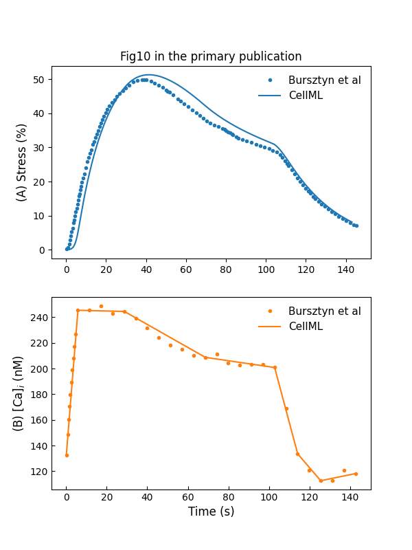
We use a curve fitting method to generate a profile close to the measured values. This is used to drive the cross-bridge model of Hai & Murphy (1988). The simulation result is shown in Figure 8. To simulate the stretch-induced contraction and relaxation, we use a piecewise linear function to construct the input . The model response to the piecewise linear function is shown in Figure 9.
![Simulation of MLC phosphorylation (A) and force production (B) stress in response to an increase in [Ca_{i}^{2+}] (C) (c.f., Fig. 9 in ).](https://pub.curvenote.com/4b04def0-9832-43bc-89b7-d4a0fb6b4036/public/simFig9-9fca058dd1534dcbfdc672a9038cb732.png)
Figure 8:Simulation of MLC phosphorylation (A) and force production (B) stress in response to an increase in (C) (c.f., Fig. 9 in Bursztyn et al. (2007)).

Figure 9:Stress development and relaxation during stretch-induced phasic contraction of human myometrium (c.f., Fig. 10 in Bursztyn et al. (2007)).
3.4Simulation of Control and Stress Production
The whole model simulation is performed by providing pacing voltage pulses mimicking the membrane depolarization. Figure 10A shows the response to a single 1-s voltage pulse from a holding potential of mV to a pulse potential of mV, while Figure 10A shows the response to a train of 10 pulses from a holding potential of mV to a pulse potential of mV, which has a duration of ms and the interval between pulses is ms.
We use a piecewise linear function to simulate a recorded human plateau potential of pregnant myometrium. Figure 11 shows the reaction of the cell model to this action potential following a holding potential of mV.
The experiment setting for Figure 10 and Figure 11 is summarized in Table 3
Table 3:Experiment setting
| Fig | Test Pulse | (mM) | Initial (nM) |
|---|---|---|---|
| 11A | single 1-s pulse of 0 mV | 16.55 | 130 |
| 11B | ten 100-ms pulses of 0 mV with 300-ms interval | 16.55 | 130 |
| 12 | simulated action potential | 2.9836 | 39 |
![Simulations of changes in [Ca_{i}^{2+}] and stress in response to pacing pulses (c.f., Fig. 11 in ).](https://pub.curvenote.com/4b04def0-9832-43bc-89b7-d4a0fb6b4036/public/simFig11-e00c2f3ac519602fcfca9c42715baefe.png)
Figure 10:Simulations of changes in and stress in response to pacing pulses (c.f., Fig. 11 in Bursztyn et al. (2007)).
![Simulation of changes in [Ca_{i}^{2+}] and stress in response to a plateau potential V_m (c.f., Fig. 12 in ).](https://pub.curvenote.com/4b04def0-9832-43bc-89b7-d4a0fb6b4036/public/simFig12-7ed04420cc121f72ac0721491b9d4e1f.png)
Figure 11:Simulation of changes in and stress in response to a plateau potential (c.f., Fig. 12 in Bursztyn et al. (2007)).
4Discussion
We implemented the model Bursztyn et al., 2007 using CellML in a modularized style which can be reused in future. We have successfully replicated all the figures and summarized detailed experiment settings for simulation in Section 3. In doing this, we noticed trivial typographical errors in parameter units and references in Table 3 of Bursztyn et al. (2007). Hence, we correct these in Table 4 to remove potential confusion.
Table 4:Correction of primary Table 3
| Parameters | primary paper | current CellML |
|---|---|---|
| 5.1449e-4 | 5.1449e-4 | |
| 5.7297e-5 | 5.7297e-5 | |
| 16.55 (18) | 2.9836 (18) | |
| 2.9836 (19) | 16.55 (19) |
Another implementation note is that the primary paper used “efflux” to indicate the direction of described in Equation (4) with a positive sign. In CellML implementation, the direction information is included in the equation. That is,
Consequently, CellML model uses a positive sign before the term in the intracellular calcium concentration equation:
Acknowledgments
The Freifeld lab is supported by the Zuckerman STEM Leadership Program and the Taub family foundation.
- Bursztyn, L., Eytan, O., Jaffa, A. J., & Elad, D. (2007). Mathematical model of excitation-contraction in a uterine smooth muscle cell. American Journal of Physiology-Cell Physiology, 292(5), C1816–C1829.
- Mitchell, M., Muftakhidinov, B., Winchen, T., Wilms, A., Schaik, B. van, badshah400, Mo-Gul, Badger, T. G., Jędrzejewski-Szmek, Z., kensington, & kylesower. (2020). markummitchell/engauge-digitizer: Nonrelease. Zenodo. 10.5281/zenodo.3941227
- Parthimos, D., Edwards, D. H., & Griffith, T. (1999). Minimal model of arterial chaos generated by coupled intracellular and membrane Ca2+ oscillators. American Journal of Physiology-Heart and Circulatory Physiology, 277(3), H1119–H1144.
- Hai, C.-M., & Murphy, R. A. (1988). Cross-bridge phosphorylation and regulation of latch state in smooth muscle. American Journal of Physiology-Cell Physiology, 254(1), C99–C106.
- Sakmann, B., & Neher, E. (1996). Single-channel recording. General Pharmacology: The Vascular System, 27(6), 1078. https://doi.org/10.1016/0306-3623(96)90073-7
- Waltemath, D., Adams, R., Bergmann, F. T., Hucka, M., Kolpakov, F., Miller, A. K., Moraru, I. I., Nickerson, D., Sahle, S., Snoep, J. L., & Novère, N. L. (2011). Reproducible computational biology experiments with SED-ML - The Simulation Experiment Description Markup Language. BMC Systems Biology, 5(1), 198. 10.1186/1752-0509-5-198
- Garny, A., & Hunter, P. J. (2015). OpenCOR: a modular and interoperable approach to computational biology. Front Physiol, 6. 10.3389/fphys.2015.00026
- Shmigol, A., Eisner, D., & Wray, S. (1998). Carboxyeosin decreases the rate of decay of the [Ca 2+] i transient in uterine smooth muscle cells isolated from pregnant rats. Pflügers Archiv, 437(1), 158–160.


