Reproducibility Study of Computational Modelling of Glucose Uptake by SGLT1 and GLUT2 in the Enterocyte
Abstract
Afshar et al. (2021) generated a computational model of non-isotonic glucose uptake by small intestinal epithelial cells. The model incorporates apical uptake via SGLT1 and GLUT2, basolateral efflux into the blood via GLUT2 and cellular volume changes in response to non-isotonic conditions. The results explain more about the role of apical GLUT2 in intestinal cell glucose absorption. Here, we used the CellML file provided by the model authors, together with SED-ML files and Python scripts, to demonstrate the reproduction of the figures in the original paper by using the associated model.
1Introduction
Glucose absorption through epithelial cells in the small intestine is known to be the main source of energy generation in humans and other species. Despite the number of investigations in recent decades McCance & Madders, 1930Wertheimer, 1934, the absorption mechanism and transporters involved under different conditions and in different species are still not clear enough and are being debated Karasov, 2017.
In 2019, Afshar et al. implemented a glucose absorption model in the enterocyte that contains all responsible transporters and was built using the CellML framework. Their model was used to study the role of SGLT1 and apical GLUT2, especially in the presence of a high glucose concentration in the intestinal lumen Afshar et al., 2019. They later extended their model to a non-isotonic glucose uptake considering water transport and changes in cell volume during the absorption process Afshar et al., 2021.
A CellML version Cuellar et al., 2003 of their model can be found in the Physiome Model Repository Yu et al., 2011. However, the CellML file itself is not sufficient to reproduce all the predictions presented in the primary article. Therefore, some SED-ML files Waltemath et al., 2011 and Python scripts were created and used with the aforementioned CellML file to reproduce the main results of Afshar et al. (2021). No modifications were made to the mathematical equations or parameters of the CellML file. All the equations and parameters can be found in the original paper. In the primary article, a validated computational model was proposed. The main goal of this paper is to show that the figures in the primary paper can be reproduced by using the correlated model in the PMR. Here, we introduce a quick instruction to reproduce each figure in the original paper.
2Model description
The model contains several relevant transporters on either side of the intestinal cell, which has three different compartments (mucosal or intestinal lumen, cell and blood or serosal). The movement of transcellular and paracellular water was based on the osmolarity difference between the two compartments involved, leading to changes in cell volume. Ions and glucose move into and out of the cell through specific transporters. Using the mathematical model, it is possible to predict membrane potentials, intracellular concentrations of glucose and electrolytes (Na, K, HCO, Cl), and the fluxes of these species. All the equations for ions’ fluxes and concentrations are described in the supplementary material in the primary paper.
The model was developed in CellML. Simulations were run until the concentration and fluxes reached steady state. A CellML encoded version of the model is available at https://
3Model results
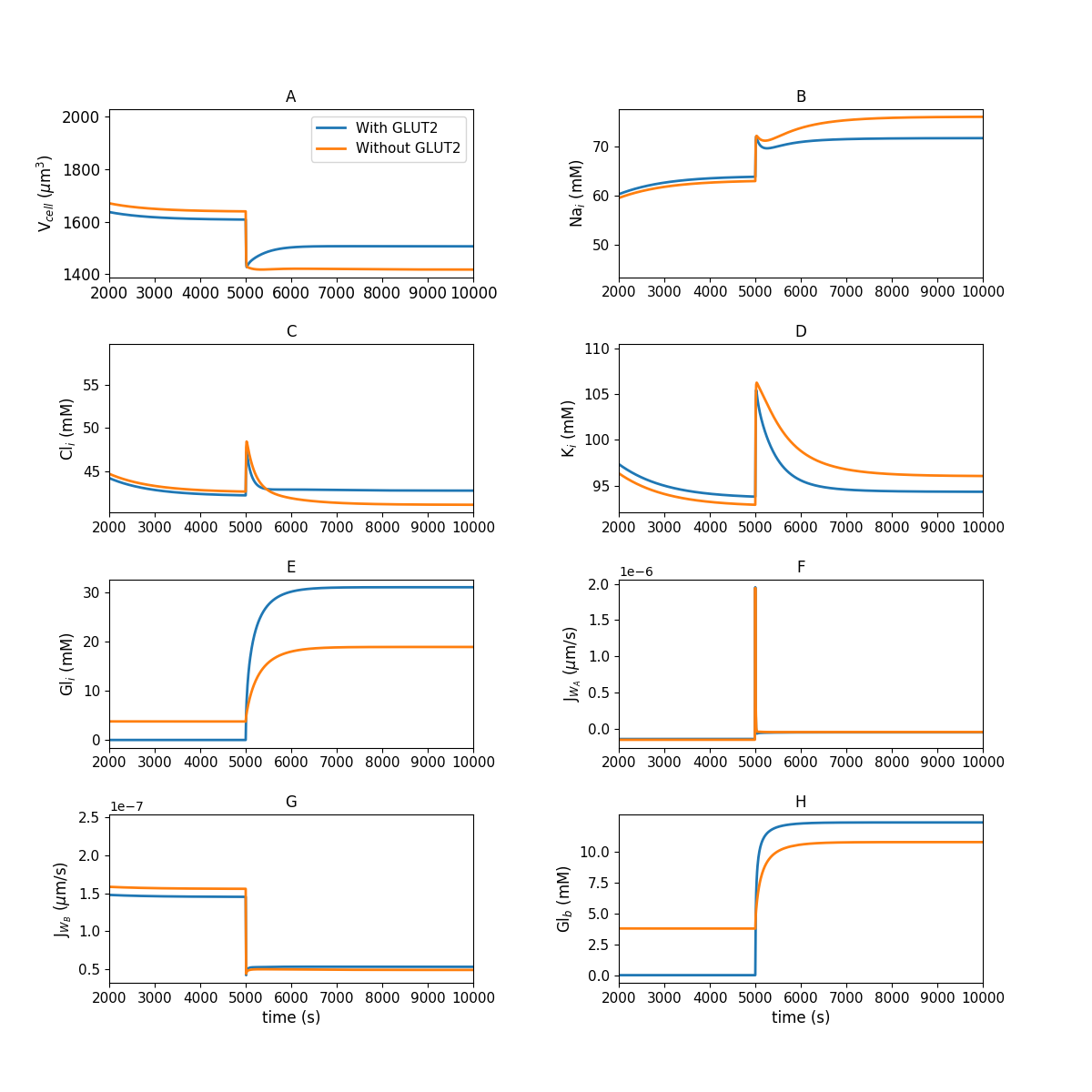
Figure 1:Model behaviour in the absence of luminal glucose ( s) and following a step change to mM luminal glucose ( s) of the simulation. (A) cell volume; (B) intracellular concentrations of sodium; (C) chloride; (D) potassium; (E) glucose; (F,G) apical and basolateral water flux; (H) blood glucose. This figure corresponds to Figure 3 in the primary paper and can be reproduced using Figure01.py.
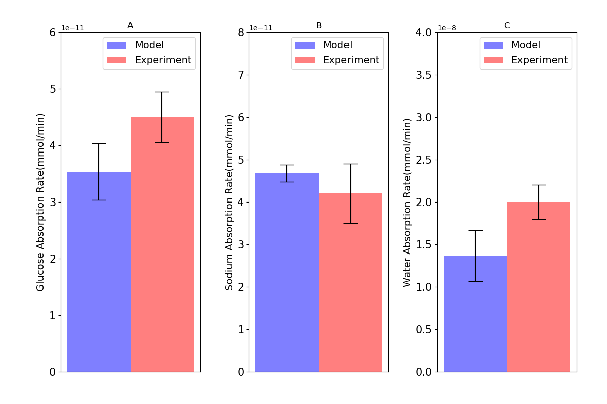
Figure 2:Absorption rates of (A) glucose; (B) sodium; and (C) water through the cell in comparison with intestinal loop data. Error bars in the model represent different values for inlet blood flow. Experimental bars are mean SE with tests. This figure corresponds to Figure 4 in the primary paper and can be reproduced using Figure02.py.
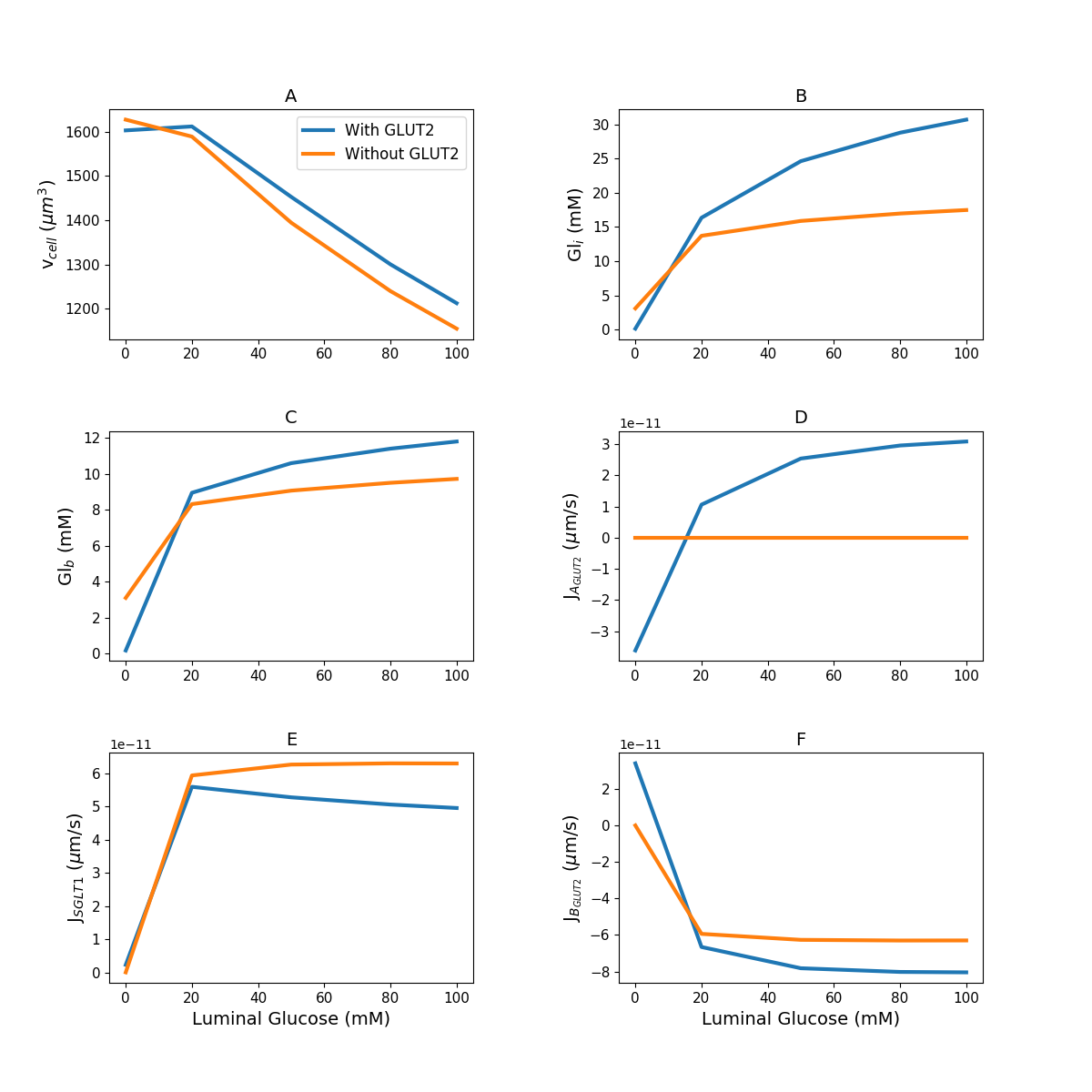
Figure 3:Model response to different luminal glucose concentration. (A) Cell volume; (B) intracellular glucose; (C) blood glucose; (D) apical GLUT2 flux; (E) SGLT1 flux; (F) basolateral GLUT2 flux. The simulation was run under five different luminal glucose concentration (, , , , and mM). Simulation parameters: number of apical GLUT2 , number of basolateral GLUT2 , number of SGLT1 , inflow blood glucose mM, inlet blood flow rate m/s, and blood volume m. This figure corresponds to Figure 5 in the primary paper and can be reproduced using Figure03.py.
![Model response to different transporter densities. (A–C) Cell volume; (D–F) intracellular glucose; (G–I) SGLT1 glucose flux; (J–L) apical GLUT2 flux; (M–O) basolateral GLUT2 flux. In each column, one transporter density is varied while the other two are held constant at the reference value [nSGLT1 = 3\times10^7, nGLUT2 (apical) = 10^8, nGLUT2 (basolateral) = 2\times10^8]. This figure corresponds to Figure 6 in the primary paper and can be reproduced using Figure04.py.](https://pub.curvenote.com/0c9258a5-09e1-4301-9d2c-9ce08ec89e5c/public/Figure04-f70021448ebd62987fe2c46260a0652f.png)
Figure 4:Model response to different transporter densities. (A–C) Cell volume; (D–F) intracellular glucose; (G–I) SGLT1 glucose flux; (J–L) apical GLUT2 flux; (M–O) basolateral GLUT2 flux. In each column, one transporter density is varied while the other two are held constant at the reference value [nSGLT1 , nGLUT2 (apical) , nGLUT2 (basolateral) ]. This figure corresponds to Figure 6 in the primary paper and can be reproduced using Figure04.py.
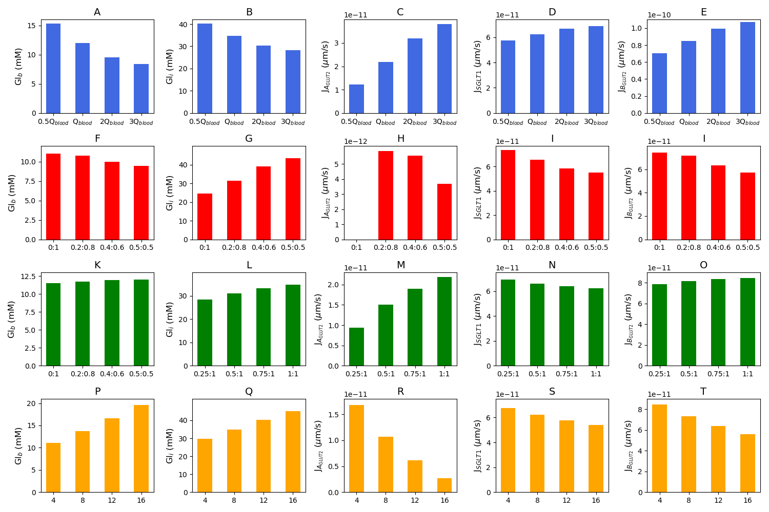
Figure 5:Blood glucose concentration, intracellular glucose concentration, apical GLUT2 flux, SGLT1 flux, and basolateral GLUT2 flux under different conditions. The first row is the model response to different blood flow rates. m/s is the baseline value of the blood flow rate (A–E). The second row shows the response to variations in the inlet blood glucose concentration (F–J). Rows three and four consider two different scenarios for GLUT2 translocation to the apical membrane. Row three shows simulations run under the assumption that apical GLUT2 is translocated from basolateral GLUT2. Different ratios between apical and basolateral GLUT2 are considered with the total number fixed (K–O). Row four shows simulations run under the assumption that apical GLUT2 is translocated from intracellular vesicles. The number of basolateral GLUT2 is fixed and labels represent the fraction of total GLUT2 in the apical and basolateral membranes (P-T). This figure corresponds to Figure 7 in the primary paper and can be reproduced using Figure05.py.
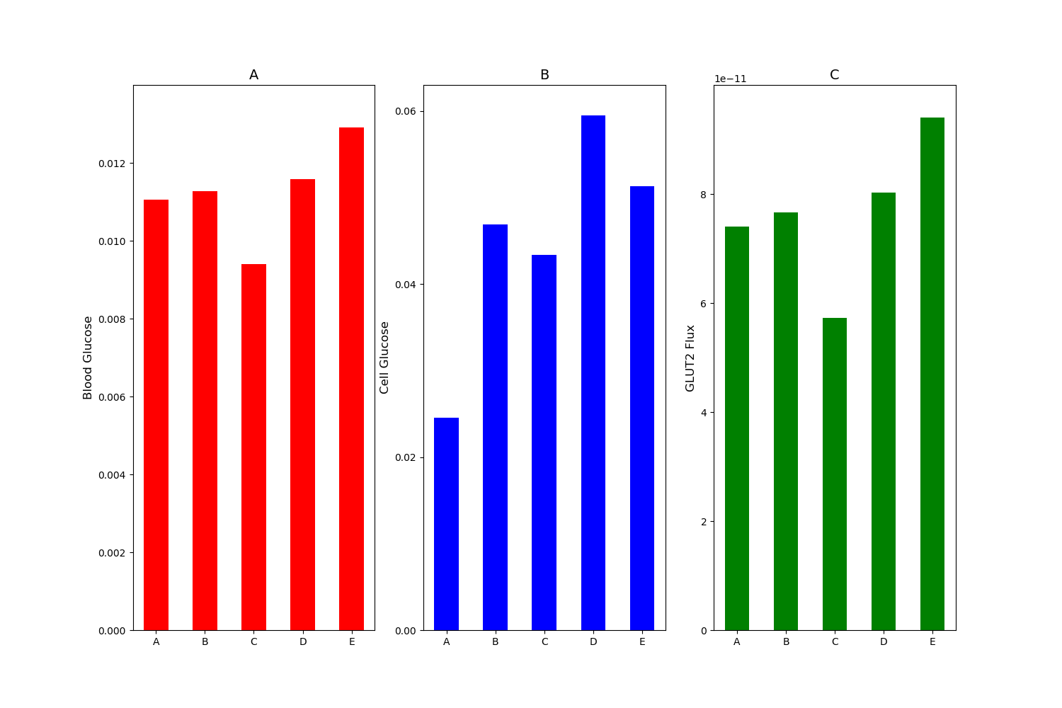
Figure 6:(A) Blood glucose; (B) intracellular glucose; and (C) glucose flux into the blood. Simulation was run under mM stimulus of luminal glucose. Bar A: baseline with no apical GLUT2. Bar B: % increase in SGLT1 and apical GLUT2 equal to times basolateral GLUT2. Bar C: baseline SGLT1 and apical GLUT2 equal to times basolateral GLUT2. Bar D: % increase in SGLT1 and apical GLUT2 equal to times basolateral GLUT2. Bar E: % increase in SGLT1 alone with no apical GLUT2. This figure corresponds to Figure 8 in the primary paper and can be reproduced using Figure06.py.
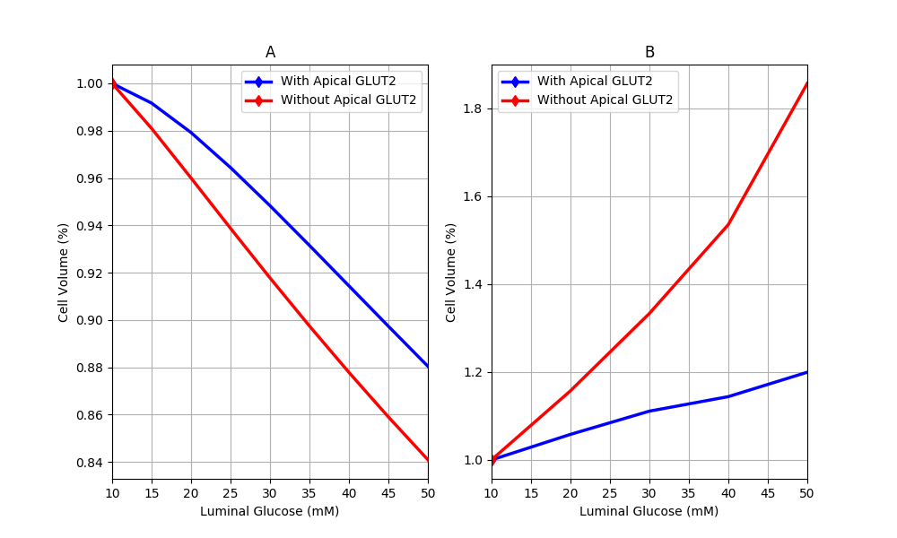
Figure 7:Cell volume behaviour in response to different luminal glucose levels in (A) our model and (B) Naftalin’s (2014) model. Values are normalised to baseline values. This figure corresponds to Figure 9 in the primary paper and can be reproduced using Figure07.py.
4Discussion
In this manuscript, we used the CellML version of the cell model developed by Afshar et al. (2021). Most of the main figures in the primary article were reproducible using the CellML code provided by the authors. Some Python code was required and can be found in https://
- Afshar, N., Safaei, S., Nickerson, D. P., Hunter, P. J., & Suresh, V. (2021). Computational Modelling of Glucose Uptake by SGLT1 and Apical GLUT2 in the Enterocyte. Frontiers in Physiology, 12. 10.3389/fphys.2021.699152
- McCance, R. A., & Madders, K. (1930). The comparative rates of absorption of sugars from the human intestine. Biochemical Journal, 24(3), 795.
- Wertheimer, E. (1934). Phloridzinwirkung auf die Zuckerresorption. Pflüger’s Archiv Für Die Gesamte Physiologie Des Menschen Und Der Tiere, 233(1), 514–528.
- Karasov, W. H. (2017). Integrative physiology of transcellular and paracellular intestinal absorption. Journal of Experimental Biology, 220(14), 2495–2501. 10.1242/jeb.144048
- Afshar, N., Safaei, S., Nickerson, D. P., Hunter, P., & Suresh, V. (2019). Computational Modelling of Glucose Uptake in the Enterocyte. Frontiers in Physiology, 10, 380. http://dx.doi.org/10.3389/fphys.2019.00380
- Cuellar, A. A., Lloyd, C. M., Nielsen, P. F., Bullivant, D. P., Nickerson, D. P., & Hunter, P. J. (2003). An overview of CellML 1.1, a biological model description language. Simulation, 79(12), 740–747.
- Yu, T., Lloyd, C. M., Nickerson, D. P., Cooling, M. T., Miller, A. K., Garny, A., Terkildsen, J. R., Lawson, J., Britten, R. D., Hunter, P. J., & Nielsen, P. M. F. (2011). The Physiome Model Repository 2. Bioinformatics, 27(5), 743–744. 10.1093/bioinformatics/btq723
- Waltemath, D., Adams, R., Bergmann, F. T., Hucka, M., Kolpakov, F., Miller, A. K., Moraru, I. I., Nickerson, D., Sahle, S., Snoep, J. L., & others. (2011). Reproducible computational biology experiments with SED-ML-the simulation experiment description markup language. BMC Systems Biology, 5(1), 1–10.
- Garny, A., & Hunter, P. J. (2015). OpenCOR: a modular and interoperable approach to computational biology. Frontiers in Physiology, 6.
- Hunter, J. D. (2007). Matplotlib: A 2D graphics environment. Computing in Science & Engineering, 9(3), 90–95. 10.1109/MCSE.2007.55


